JunPus thermal compounds deliver advanced heat dissipation solutions tailored for high-performance AI chips, CPUs, GPUs, and 5G base stations.
Engineered for cutting-edge semiconductor technologies,
our patented thermal pastes optimize thermal conductivity, ensuring stable performance under intensive workloads. Trusted across electronics, data centers, and telecommunications
A nano-diamond thermal grease for processor and high-power electronic interfaces. Explore the contact structure, material properties and application process.
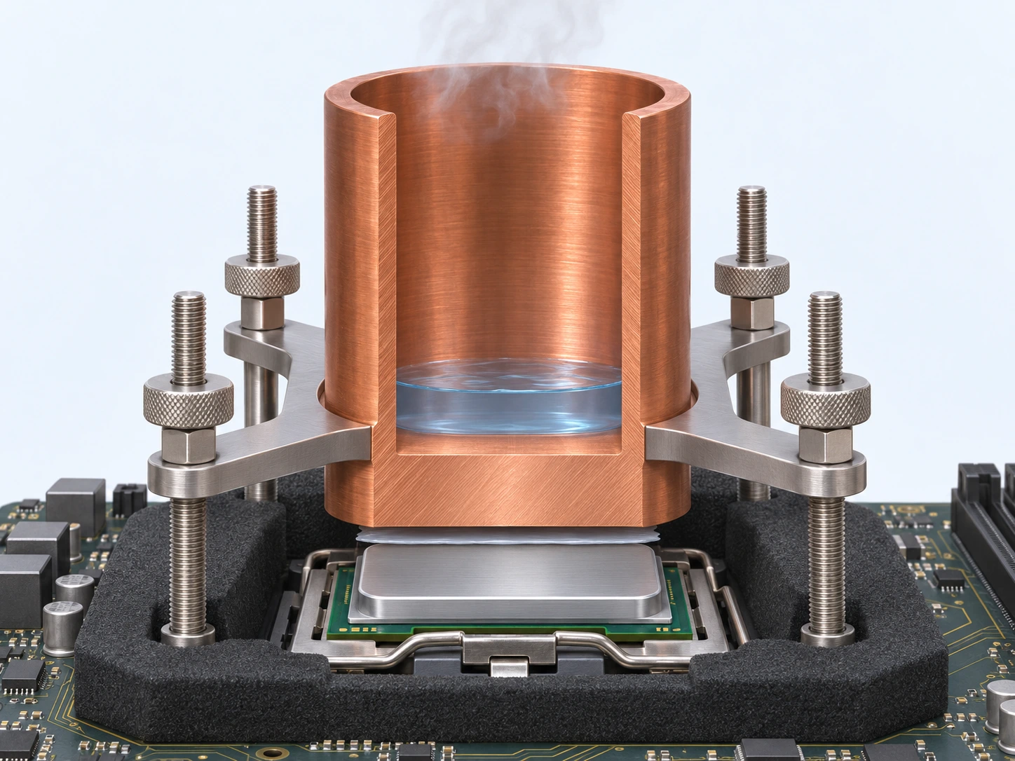
The solid base contacts the processor. Coolant remains inside the sealed channels.
02
JP-D9000 contact layer
The proposed grease location is between the processor heat spreader and the cold-plate base.
03
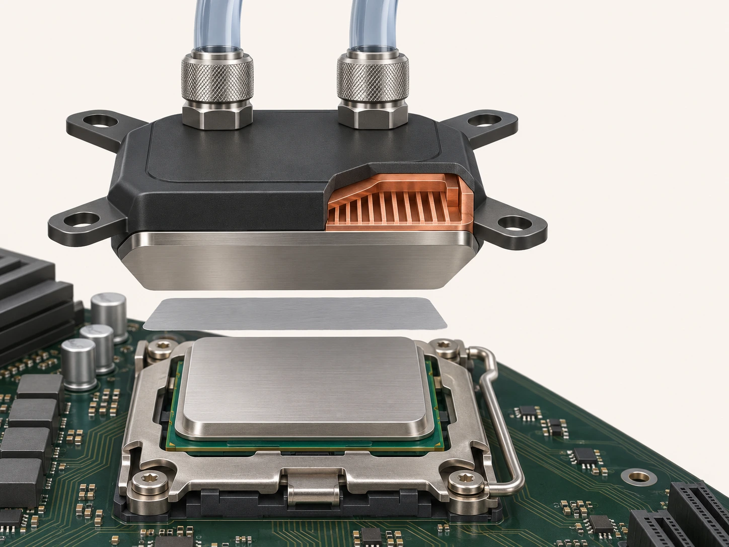
Processor in its socket
The visible silver surface is the package heat spreader. The silicon die is underneath it.
AI-generated technical illustration. Exploded spacing and grease thickness are exaggerated; the interface is a paste, not a preformed pad.
JP-D9000 · PRODUCT OVERVIEW
Nano-diamond thermal grease for demanding chip interfaces.
JP-D9000 is a gray, nano-diamond-based thermal grease for the contact between a heat-generating electronic component and its cooling surface. JunPus identifies computer processors, graphics processors and high-power electronic modules among its intended application categories.
The material belongs in the interface, not in the coolant. After the approved assembly process brings the mating surfaces together, the grease forms a contact layer that helps bridge the small surface irregularities between them. The complete cooling result still depends on the component, mounting stack and cooler.
01
CPU cooling assemblies
Use at the approved contact between the processor and a heat-sink or cold-plate base. The illustration above shows a processor with an integrated metal heat spreader.
02
GPU thermal interfaces
The company technical sheet includes graphics processors. GPU packages and cooler mounting arrangements vary, so use the component maker’s requirements for the actual contact surface, coverage and assembly load.
03
High-power electronic modules
Consider the material for an approved component-to-cooling-substrate contact. Check geometry, isolation needs and operating conditions rather than transferring a CPU mounting procedure to another module.
MATERIAL CHARACTERISTICS
A controlled interface. A continuous heat path.
The company sheet describes a low-flow paste that is easy to apply and wipe, resists hardening and maintains its viscosity during extended use. Historical material-test data are presented below.
Thermal conductivity
8.9 W/m·K
Published product property; assembly performance depends on the complete thermal path.
Stated viscosity
5,500,000 mPa·s
Supplier-stated viscosity. Compare under the same measurement method and temperature.
Use the grease as a thin, mechanically clamped thermal contact. It is not a replacement for a specified thermal pad, a required dielectric layer, an adhesive or a structural gap-filling material.
The sheet describes the material as electrically non-conductive, but this is not an electrical-insulation approval for an assembly. Keep the application within the approved contact area and follow the equipment maker’s electrical-safety requirements.
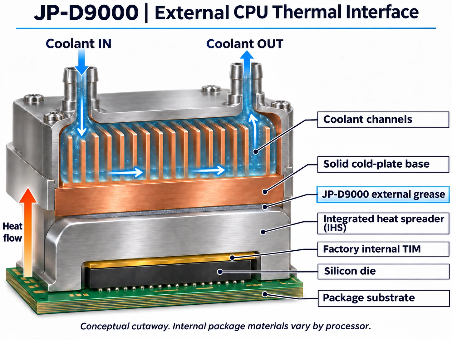
LOCATE THE MATERIAL
On the processor lid. Under the cooler base.
The external JP-D9000 layer sits between the processor’s metal lid and the cold-plate base. The silicon die remains inside the processor package.
Conceptual cutaway. Internal package materials vary by processor.
TEMPERATURE RANGE
From cold starts to elevated temperatures.
−50 °C+150 °C
Stated operating-temperature range: −50 to 150 °C.
Thermal conductivity
8.9 W/m·K
Material
Gray thermal grease
Match the product range to the interface temperature in your assembly.
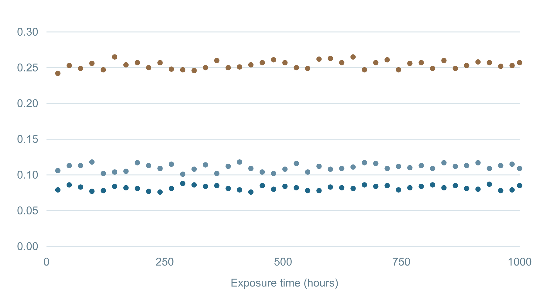
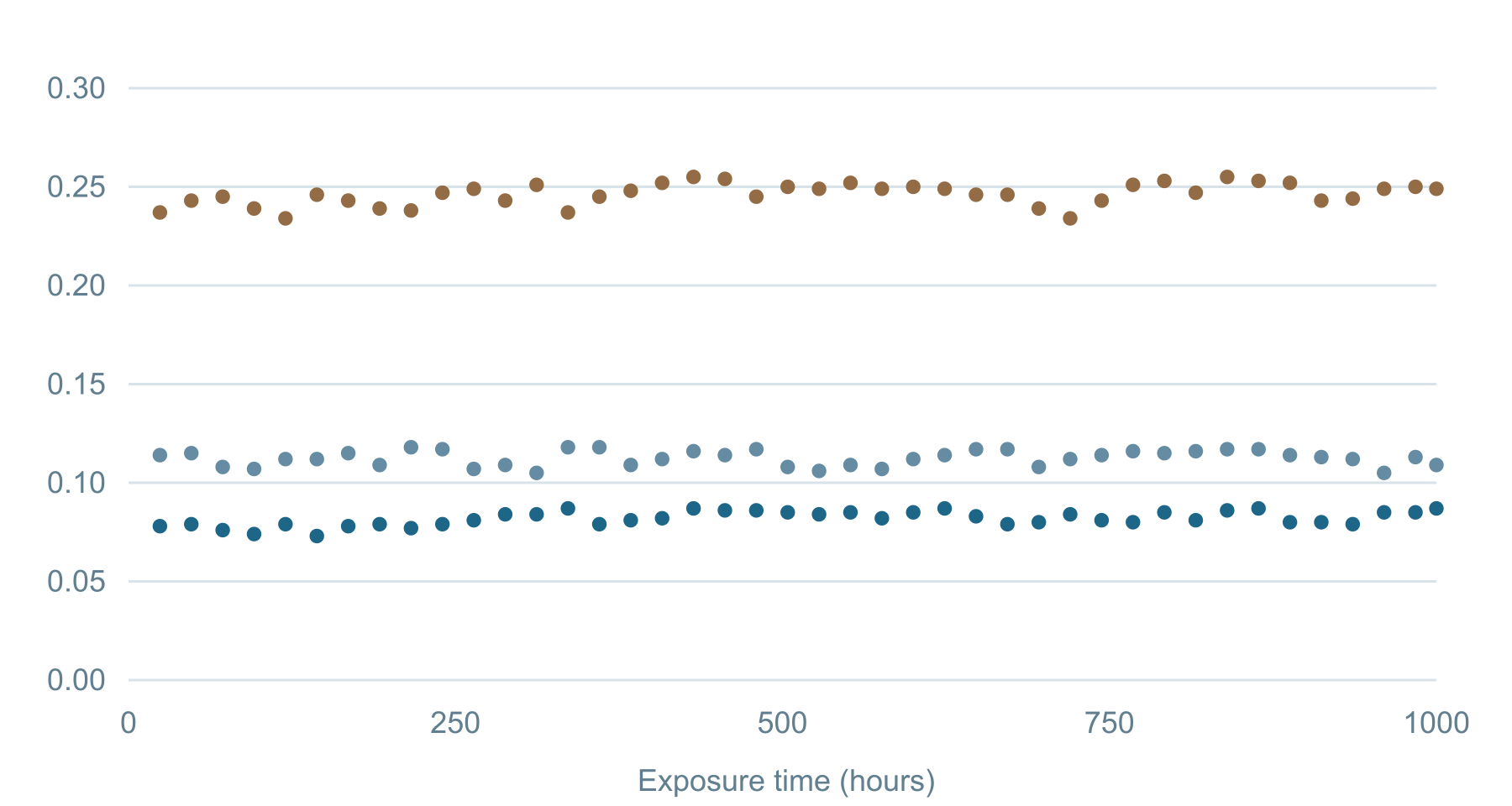
HISTORICAL MATERIAL TESTS · 2012
Measured across thermal stress.
Thermal-resistance readings across 1,000 hours of temperature cycling and heat/humidity exposure. Select a measurement pressure to compare the recorded data.
20 psi40 psi60 psi
NRT008 · VERSION 1.0
Thermal cycling
−40 to 125 °C · 1,000 hours
Thermal resistance (°C·cm²/W)
Discrete historical measurements; first reading at 24 hours.
NRT007 · VERSION 1.0
Heat & humidity
85 °C / 85% RH · 1,000 hours
Thermal resistance (°C·cm²/W)
Discrete historical measurements; first reading at 24 hours.
2012 material tests: 42 specimens, daily sampling and a 100 W / 60-minute measurement procedure. Different specimens were evaluated over time; these are historical test results, not a current-batch certificate.
HISTORICAL EXTREME-COOLING REVIEW · 2013
The interface in an extreme-cooling test.
Solid pot baseExternal greaseCPU package
Historical test concept · Generic cooling-pot illustration
Heat-flow directionSilicon die → processor lid → external grease → copper pot base → coolant
The contact arrangement is the key: the cooling pot’s solid base meets the processor’s metal lid through an external grease layer. Liquid nitrogen remains inside the pot, separate from the processor and the interface material.
AI-generated historical test illustration, not an installation guide. Cryogenic testing requires specialist equipment and procedures.
In a 2013 HWBOT roundup, der8auer included D9000 among 26 thermal compounds. The review describes liquid-nitrogen tests at stated temperatures of −50 °C and −150 °C with an Intel Core i7-3770K at 5 GHz.
This historical third-party review is separate from the company sheet’s stated −50 to 150 °C product operating range.
Historical review context only; this does not establish current-product cryogenic qualification.
Confirm the heat-source surface, cold-plate base, flatness, applied amount and mounting load.
Control the operating conditions.
Record coolant temperature, flow, heat load, ambient conditions and sensor locations so tests can be repeated.
Evaluate thermal transitions.
Check the interface across the intended temperature cycles and inspect material movement using a defined procedure.
Place the thermal grease at the external contact between the heat source and the solid cold-plate base, outside the sealed coolant circuit.
SELECT FOR THE COMPLETE ASSEMBLY
Match the material to the contact and duty cycle.
01
Start with the component and surfaces.
Identify the processor or module, its approved contact face and the cooler-base material. Check surface condition, flatness, contact area and any required electrical insulation.
02
Confirm the temperature conditions.
Compare the intended interface temperatures and thermal transitions with the approved product specification. A historical extreme-cooling review does not extend the company sheet’s stated operating range.
03
Define the mechanical process.
Specify the approved applied amount, coverage, bond-line thickness and mounting load. These must suit the hardware; the report’s measurement pressures are not installation instructions.
04
Confirm the product and process.
Match the product specification and package format to the assembly. Compare thermal-resistance data only under the same pressure, bond-line thickness and measurement conditions.
APPLICATION & HANDLING
Apply to the contact. Keep the process repeatable.
Prepare the approved surfaces.
Follow the equipment maker’s cleaning and preparation process. Inspect the mating faces before applying the material, and keep contaminants and old interface residue out of the new contact.
Use the specified amount and coverage.
Place the grease only within the approved heat-transfer area. Use a validated application method for the component and package. This page does not prescribe a universal dot pattern, dose or layer thickness.
Assemble using the hardware requirements.
Bring the mating surfaces together and secure the cooler using the approved sequence and load. Check the resulting coverage and any squeeze-out using the production inspection method.
Verify thermal performance.
Measure the completed assembly at its intended operating conditions. Record the setup so that results can be compared across samples and repeated after thermal cycling.
Protect the material between uses.
For bulk material, the company sheet instructs uniform mixing before use and immediate resealing after use. Do not add diluents or other ingredients. Confirm package-specific handling with JunPus.
15–25°C
Company-sheet storage guidance Relative humidity below 80%; do not refrigerate. The sheet lists 720 days at 25°C. Confirm the applicable shelf-life date and current package instructions.
Follow the equipment manufacturer’s approved preparation, application and mounting procedure.
NANO DIAMOND THERMAL GREASE D9000
Thermal Resistance (℃·cm²/W)
0.08
Thermal Conductivity (W/m·K)
8.9
Specific Gravity (g/cm³)
2.7
Viscosity (mPa·s)
5,500,000
Color Appearance
Gray
Model Number
JP-D9000
JP-D9000 is a cutting-edge thermally conductive compound designed to meet the rigorous demands of modern AI chips, semiconductors, and high-performance electronics. Made from high-purity thermal conducting materials, its nanoscale-treated molecular structure ensures superior thermal conductivity. Formulated with nanodiamond powder and silicone fluids, JP-D9000 delivers exceptional heat dissipation for applications requiring advanced thermal management.