JunPus thermal compounds deliver advanced heat dissipation solutions tailored for high-performance AI chips, CPUs, GPUs, and 5G base stations.
Engineered for cutting-edge semiconductor technologies,
our patented thermal pastes optimize thermal conductivity, ensuring stable performance under intensive workloads. Trusted across electronics, data centers, and telecommunications
Thermal grease for LED module-to-heatsink interfaces.
JP-DL700 is a gray thermal grease identified by JunPus for LED, IC and electronics-module interfaces. Explore the contact layer behind the LED board and the thermal path into the heat sink.
↓
LED board → thermal interface → heat sink. The grease sits at the mechanically clamped heat-transfer contact. It does not coat the LED optics or exposed circuit components.
Conceptual assemblies illustrate thermal-interface locations. Select the material and process for the actual hardware.
CURRENT OFFICIAL PRODUCT PAGE
Use the stated values. Qualify the process.
Thermal conductivity
4 W/m·K
Thermal resistance
0.147 °C·cm²/W
Viscosity
700,000 mPa·s
The website does not state the viscosity test method or temperature. The resistance value also needs its measurement conditions before a design comparison. These figures do not establish dispensing force, LED temperature reduction or fixture lifetime.
MODULAR STREET-LIGHT CONCEPT
A defined path behind every LED module.
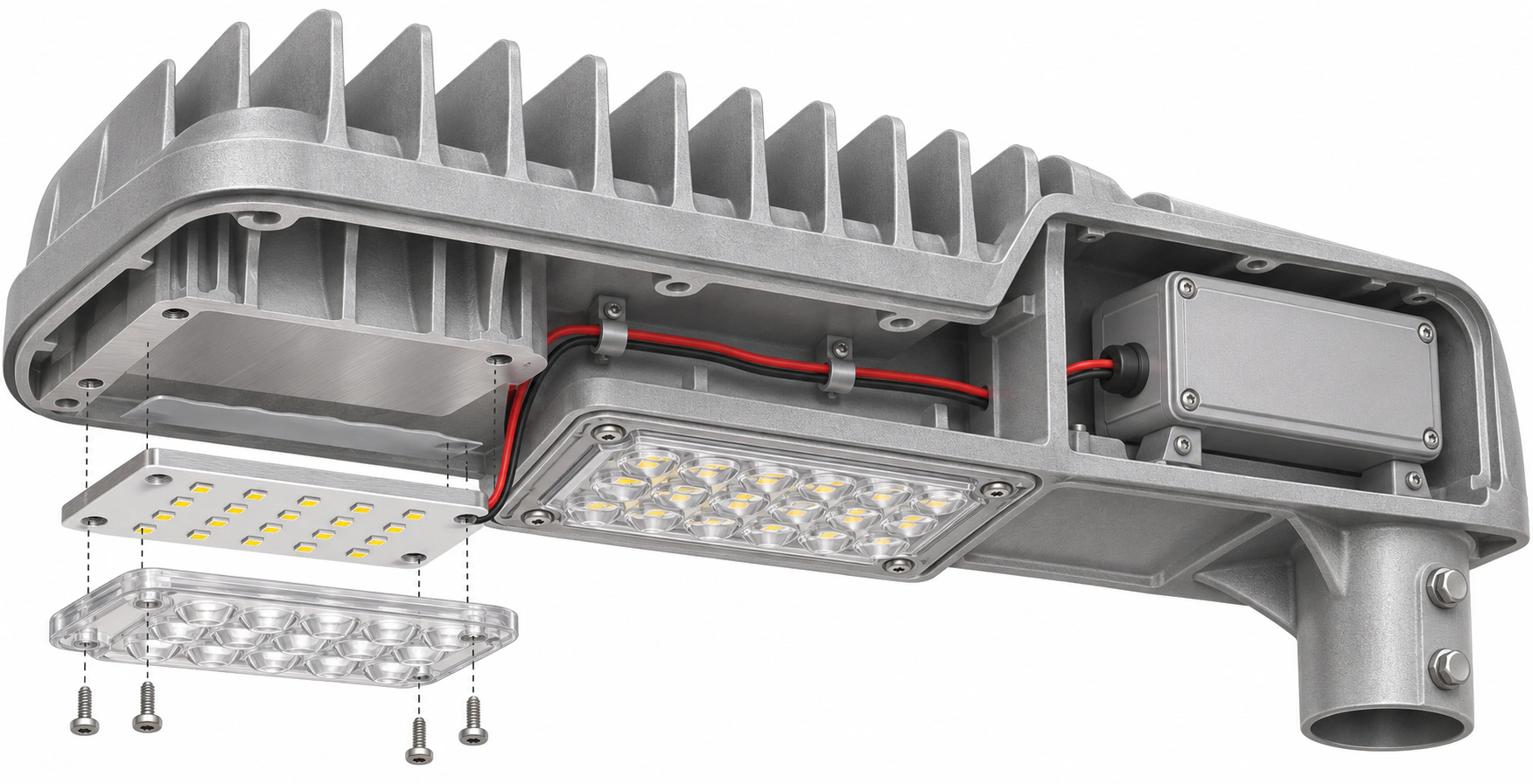
A modular road-lighting assembly can use separate LED boards mounted to a metal heat-sink housing. The interface is behind each board, between its approved thermal-contact face and the corresponding metal mounting surface.
JP-DL700 contact locationSwipe sideways to view the full assembly
AI-generated technical illustrationJP-DL700 LED thermal-interface concept for a modular streetlight. One LED module is exploded to expose the proposed board-back grease contact and metal heat-sink surface; another remains assembled. The driver enclosure is separate.
CONTACT DETAIL
Behind the LED board.
The material is placed at the board’s rear thermal-contact face, against the metal heat-sink housing. The LEDs face the optical array on the opposite side.
Metal heat-sink contact
External DL700 interface
LED board backside
LED emitters and optics
Heat-sink housing
The metal mounting surface receives heat from the LED boards and rejects it through the surrounding structure.
JP-DL700 contact location
A thin contact layer behind each LED board. Final coverage and thickness depend on the approved assembly.
LED boards and optical arrays
The emitting side faces the optics. Keep grease away from lenses, emitters and exposed circuitry.
Separate driver enclosure
The rear-compartment driver is not part of the illustrated LED-board grease contact. Its own thermal design requires separate review.
Select the interface for the board’s heat load and contact area, not total lamp wattage alone. Board heat load, contact area, ambient conditions, enclosure design and junction temperature must be evaluated.
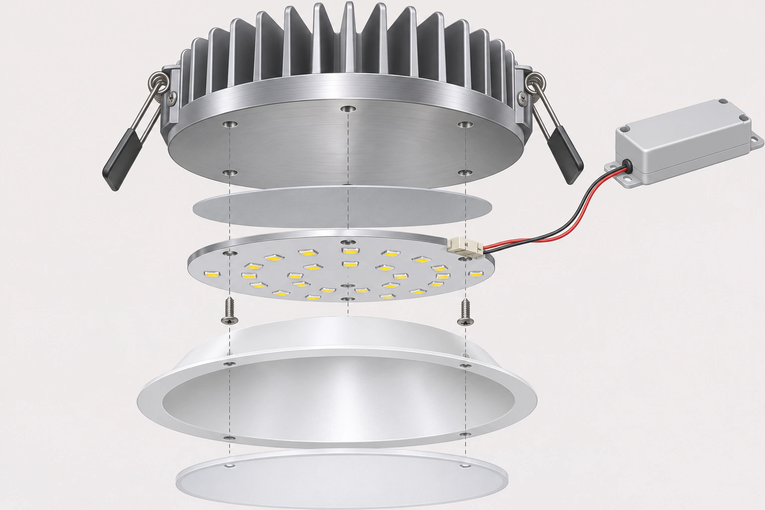
This downlight-style assembly uses a circular LED board beneath a heat sink, with a reflector and diffuser on the light-emitting side. Other fixtures may use a different stack, an insulating interface, a remote driver or an integrated housing.
JP-DL700 contact locationSwipe sideways to view the full assembly
JP-DL700 thermal greaseBetween board and heat sinkHeat sinkLED boardSeparate driver
AI-generated technical illustrationJP-DL700 thermal grease contact location in a conceptual LED downlight: between the rear thermal face of the LED board and the heat sink, separate from the reflector, diffuser and electrical driver.
CONTACT DETAIL
Keep the two sides distinct.
The metal backside transfers heat toward the sink. The light-emitting side faces the reflector and diffuser. The driver and wiring remain separate from this grease contact.
Heat-sink base
DL700 contact location
LED board
Reflector and diffuser
Finned heat sink
Heat spreads from the contact surface into the metal body and fins.
External contact layer
Evaluate JP-DL700 only where the design permits a grease interface.
Circular LED board
The board’s emitting face points toward the reflector and diffuser below.
Driver and wiring
Shown for assembly context. Do not apply grease across connectors, wiring or exposed electronics.
AI-generated technical illustrations. Separation and highlighted interface layers reveal the contact locations. Follow the fixture maker’s assembly requirements.
Separate the light path, the circuit and the thermal contact.
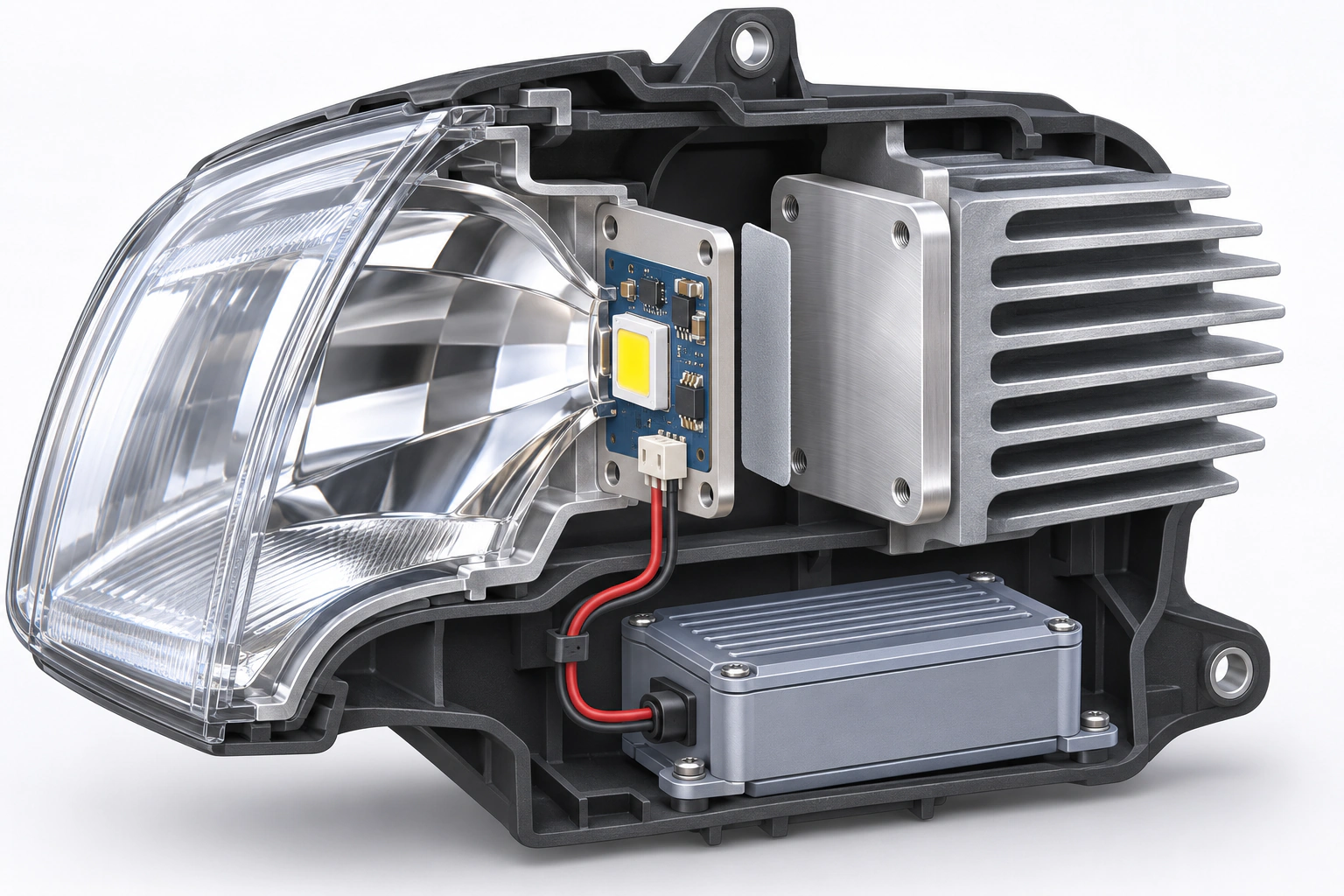
A headlamp combines optics, a driven LED assembly and a heat-rejection structure. This concept exposes the contact behind the LED carrier while keeping its electrical connection separate and easy to follow.
JP-DL700 contact locationSwipe sideways to view the full assembly
JP-DL700 thermal greaseBehind the LED carrierLED board / carrierHeat sinkLED driver
AI-generated technical illustrationEV LED headlamp thermal-interface concept: the grease contact is behind the LED carrier, between its metal mounting face and the heat sink. Driver wiring connects to the board and does not pass through the thermal interface.
Thermal path
LED package → board/carrier → external interface → heat sink. The interface belongs on the approved rear contact surface, away from the emitter and optics.
Electrical path
Driver → wiring connector → LED board. Keep the electrical routing and all required insulation intact.
Automotive engineering concept. DL700 suitability requires the lamp maker’s application-specific validation; no vehicle fitment or automotive approval is claimed.
SOLAR INVERTER POWER-STAGE CONCEPT
Power-module cooling inside a solar inverter.
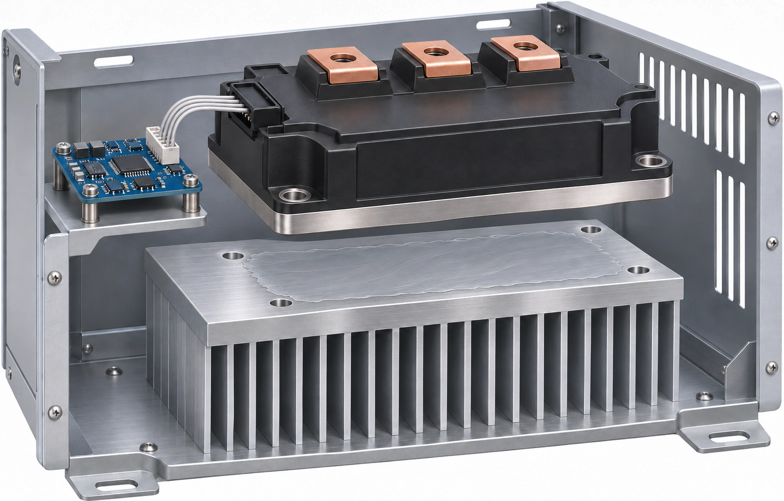
In an inverter power stage, semiconductor modules transfer heat through their metal baseplates to a heat sink or cold plate. The relevant thermal interface is external to the closed power module, at its baseplate-to-cooler contact.
JP-DL700 contact locationSwipe sideways to view the full assembly
AI-generated technical illustrationSolar inverter thermal-interface concept: a thin grease coating sits on the metal heat-sink contact face beneath the power-module baseplate. The module’s internal dielectric and semiconductor layers remain intact.
Correct contact location
Power-module baseplate → external TIM → heat sink. The diagram does not place grease on photovoltaic cells, exposed semiconductor dies or internal solder layers.
Keep the insulation system
The external grease does not replace the module’s dielectric structure or any additional insulation required by the equipment maker.
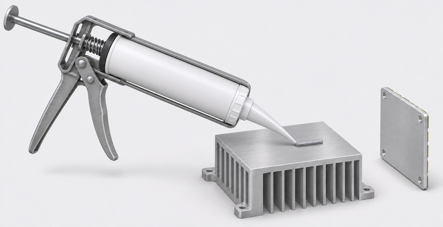
A generic dispenser can illustrate how material is placed on an approved metal contact face before assembly. The AI-generated technical illustration shows a generic, unbranded cartridge gun, not confirmed JP-DL700 supplied packaging or a validated dispensing process.
JP-DL700 contact locationSwipe sideways to view the full assembly
AI-generated technical illustrationConceptual cartridge-gun application at an LED heat-sink mounting face. Confirm the JP-DL700 package, dispensing equipment, nozzle, amount and final coverage before selecting a production process.
Generic cartridge dispenser
A historical company quotation contains common cartridge shapes, but no model-labelled DL700 cartridge photograph was verified.
Nozzle and placement
Illustrative only. No nozzle bore, extrusion pressure, bead pattern or material dose is specified by this drawing.
Approved contact face
The exposed flat metal surface is the proposed mating area. The separate board shows its metal backside. The small bead is illustrative, not a defined pattern, dose or final assembled layer.
The verified DL700 product photograph remains the original product image at the top of this page. Cartridge availability must be confirmed. Do not relabel a generic tube or another model’s package as JP-DL700.
BEYOND THE LIGHT ENGINE
ICs and electronics. Review each interface.
IC-to-heat-sink contact
A DL700 company diagram explicitly places the grease between an IC contact surface and a heat sink. Actual package and mounting details still govern the design.
PCB heat-sink interfaces
The company catalog includes PCB heat-sink interfaces in the DL700 application group. Confirm whether the contact is metal, insulated or requires another interface format.
Driver or power-module evaluation
Check the component maker’s approved heat-transfer face. Do not infer a particular power module, electrical isolation rating or continuous power capability from the general electronics category.
Thermal grease is not an adhesive, a general-purpose gap filler or a substitute for required electrical insulation. Do not dispense over exposed circuits.
FROM CONCEPT TO PRODUCTION
Validate the assembly under its real conditions.
Confirm the contact stack.
Check the LED or component package, mounting-face geometry, required isolation and approved mating materials.
Define the application process.
Agree the package format, dispensing or printing method, amount, coverage, assembly load and inspection method with JunPus and the equipment maker.
Measure the complete system.
Record electrical input, relevant heat load, ambient temperature, airflow and sensor locations. Evaluate LED junction-temperature limits using the component maker’s method.
Review reliability requirements.
Qualify the assembled fixture for its environment and service conditions rather than treating material-level tests as an entire lamp certification.
Historical DL700 reports cover heat/humidity, high-temperature storage and temperature cycling under their specified material-test conditions. Their 100 W heater setting is not a lamp wattage rating.
Request a sample. Evaluate it in your application.
Contact JunPus to discuss JP-DL700 sample availability and evaluate the material under your actual operating conditions. Share your contact surfaces, assembly process and thermal requirements to assess suitability for your design.
JP-DL700 is a gray thermal grease identified by JunPus for LED, IC and electronics-module interfaces. Explore the contact layer behind the LED board and the thermal path into the heat sink.